Single Phase Rotary Isolator Switch Wiring Diagram

Awesome Wiring Diagram For Neon Lights Diagrams Digramssample Diagramimages Wiringdiagramsample Wiringdi Fan Light Switch Light Switch Wiring Bathroom Fan

Electrical In 2020 Light Switch Wiring House Wiring Installing A Light Switch

The Complete Guide Of Single Phase Motor Wiring With Circuit Breaker And Contactor Diagram Electrical Circuit Diagram Circuit Diagram Electrical Wiring Diagram

Wiring Diagram For Two Switches To Control One Receptacle Light Switch Wiring Wire Switch Electrical Wiring

Manual Changeover Switch Wiring Diagram For Portable Generator Transfer Switch Generator Transfer Switch Outlet Wiring

Electrical Wiring Diagrams For Air Conditioning Systems Part Two Electrical Knowhow Electrical Diagram Air Conditioning System Basic Electrical Wiring
Wiring diagram isolator switch new wiring diagram alternator to.
Single phase rotary isolator switch wiring diagram.

4 Way Switch Wiring 4 Way Light Switch Light Switch Wiring 3 Way Switch Wiring

Electrical Engineering World Electrical Wiring Electrical Engineering Electricity

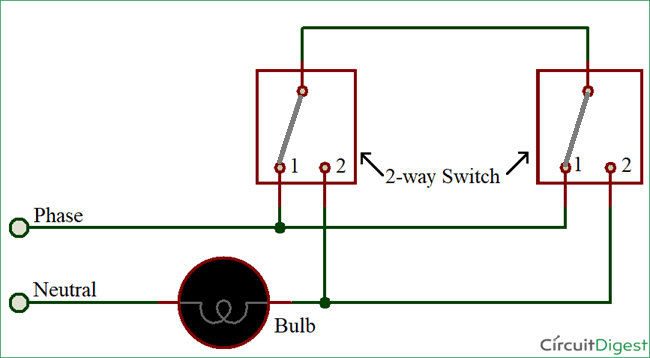
Two Way Light Switch Connection Electrical Switch Wiring Electrical Switches Light Switch

On Off Three Phase Motor Connection Power Control Electrical Circuit Diagram Basic Electrical Wiring Electrical Wiring Diagram

Forward Reverse Three Phase Motor Wiring Diagram Non Stop Engineering Electrical Projects Electrical Circuit Diagram Electronic Engineering

4 Way Switch Wiring Diagram Multiple Lights Aol Image Search Results Light Switch Wiring Electrical Switches 3 Way Switch Wiring

Pin By Cat6wiring On Ceiling Fan Wiring Diagram Ceiling Fan Wiring Light Switch Wiring Ceiling Fan With Light
Brake Lever Wiring Diagram Diagram Base Website Wiring Diagram Venndiagrammemes Edocentrico It

Generator Changeover Switch Wiring Diagram As Well As Solar Transfer Switch Generator Transfer Switch Electrical Projects
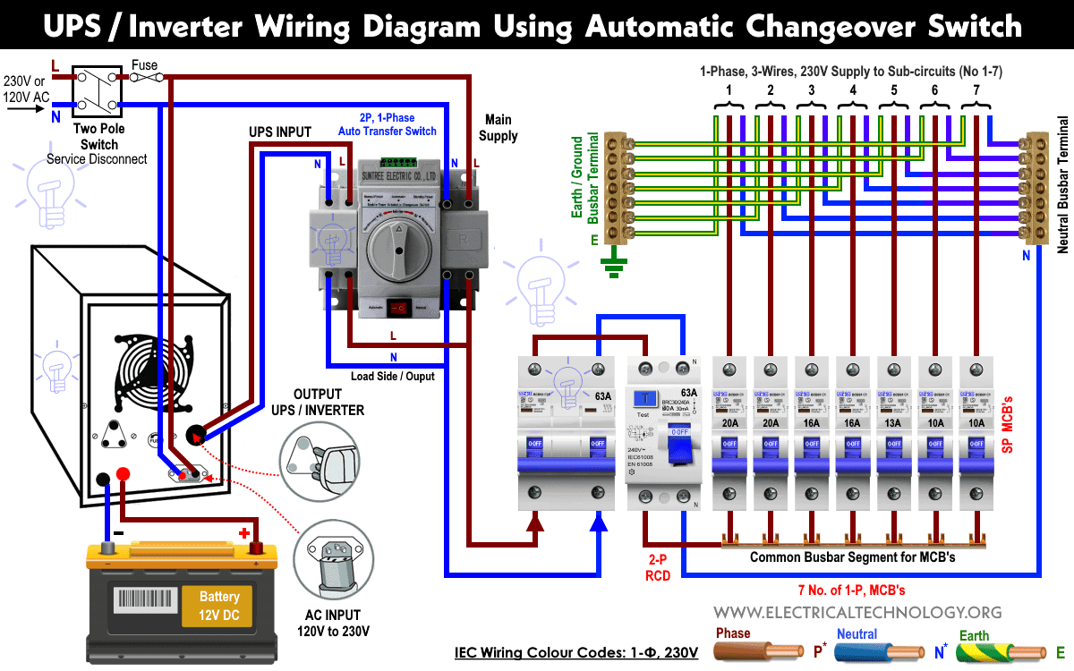
How To Wire Auto Manual Changeover Transfer Switch 1 3 Phase

Airbag Switch Box Diagram Electrical Work Wiring Diagram Air Ride Air Bag Impala

3 Way Dimmer Switch For Single Pole Wiring Diagram Light Switch Wiring Dimmer Switch 3 Way Switch Wiring
How To Connect A 2 Way Switch With Circuit Diagram

Electrical Wiring Single Phase Motor Starter Wiring Diagram Submersible Well P 2 Way Switch Wir Projetos Eletricos Eletrica Residencial Instalacoes Eletricas

Contactor Electricity Capacitors Manufacturing

A Complete Guide Of Ammeter Selector Switch Wiring Diagram With Current Transformers And Ammeter Diagram Circuit Diagram Current Transformer
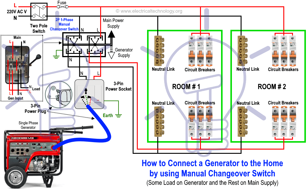
How To Connect A Portable Generator To The Home Supply 4 Methods

Elegant Example Atv Winch Rocker Switch Wiring Pictures Atv Winch Winch Diagram
Https Encrypted Tbn0 Gstatic Com Images Q Tbn 3aand9gcra70ebhjtgmctrlfmbzxhjcdmhjvupdmvvfrdtu7w7v5dejxwd Usqp Cau
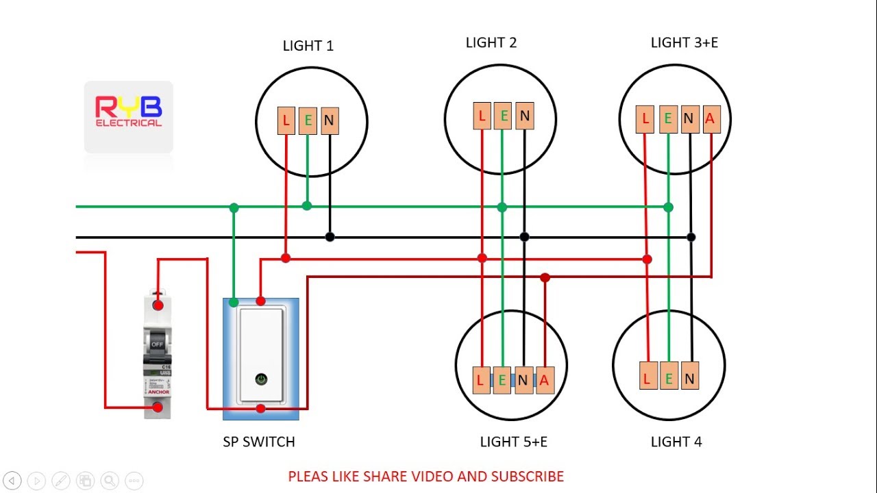
Emergency Light Switch Wiring Diagram Youtube

Extractor Fan Wiring Diagram Bathroom Extractor Fan Shower Extractor Fan Bathroom Fan

New Wiring Diagram Ac Sharp Inverter Diagram Diagramtemplate Diagramsample Check More At Https Servisi Co Wiring D Pv System Diagram Solar Panel Companies
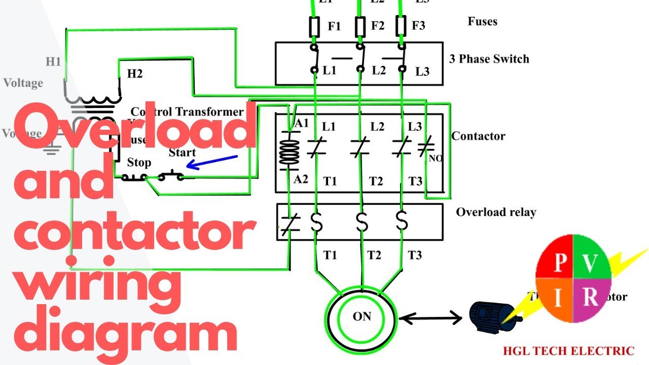
How To Wire A Contactor And Overload Start Stop 3 Phase Motor Control Youtube

Split Ac Wiring Diagram Indoor Outdoor Single Phase Youtube In 2020 Ac Wiring Split Ac Indoor Outdoor
Source : pinterest.com
